What To Know Before Buying Used Metalworking Equip

 Group Definition: Coordinate 1 = Leading Axis (incremental feedback); Coordinate 3 = Driven Axis (incremental feedback). Step 1: Modify machine data accordingly. Step 2: Set NCK PLC interface signals: - Axis1 setting: DB31, DBX29.4 = 0; DB31, DBX29.5 = 1.- Axis3 setting: DB31, DBX29.4 = 0.- Machine ready signal setting: DB31, DBB101. Step 3: Set MD 37110: GANTRY_POS_TOL_WARNING and MD 37120: GANTRY_POS_TOL_ERROR to the maximum coordinate value. Step 4: Complete settings and adjust machine parameters for matching. 9. Conclusion Synchronous axis function is a practical foundational technology in machine applications, crucial for achieving required precision based on machine rigidity and structure configurations.

Discussion on Issues in CNC Turning Processes

0 Introduction An ideal machining program should not only ensure the production of qualified workpieces that meet the design specifications but also fully utilize and enhance the functions of CNC machine tools. CNC machines are highly efficient automated equipment, boasting efficiency levels 2-3 times higher than conventional machines. To fully leverage this advantage, it is essential to perform a thorough process analysis on the workpiece before programming and choose the most economical and rational process plan based on specific conditions. Inadequate consideration of CNC machining processes can significantly impact machining quality, production efficiency, and processing costs. This article aims to explore and summarize some process issues in CNC turning based on practical production experience.  1 Division of CNC Machining Processes When machining parts on CNC machines, processes are relatively concentrated. Ideally, all operations should be completed in a single clamping. Common principles for dividing processes include:  Ensuring Accuracy CNC machining allows for process concentration, enabling rough and finish machining to be completed in one clamping to ensure part accuracy. However, if thermal deformation and cutting force deformation significantly affect machining accuracy, rough and finish machining should be performed separately.  Improving Production Efficiency To reduce the number of tool changes and save tool change time in CNC machining, all areas requiring the same tool should be completed before switching to another tool. Additionally, empty travel should be minimized, and the tool should follow the shortest path to reach various machining areas. In practical production, CNC machining processes are often divided according to tools or machining surfaces.  2 Selection of Tool Position Points for Turning Tools In CNC machining, the CNC program should describe the tool's movement trajectory relative to the workpiece. In CNC turning, the formation of the workpiece surface depends on the position and shape of the moving cutting edge envelope. However, only the trajectory of a selected point on the tool system needs to be described in the program. This point is known as the tool position point, which represents the tool's location. The machining trajectory described by the program is the movement path of this point. Theoretically, any point on the tool can be chosen as the tool position point in CNC turning. However, to facilitate programming and ensure machining accuracy, the selection of the tool position point follows certain rules and techniques. Generally, the following rules are observed: - Choose a point on the tool that can be directly measured, ensuring consistency with the point measured during tool length presetting.- If possible, the tool position point should directly relate to dimensions with high accuracy requirements or those difficult to measure.- The chosen tool position point should allow for the tool's extreme position to be directly reflected in the program's movement commands.- Programmers should adopt a habitual tool position point selection method, avoiding frequent changes.- The selected tool position point should be graphically marked in the tool adjustment diagram.  3 Termination Position of the Tool in Layered Cutting When the machining allowance of an external cylindrical surface is substantial, multiple passes of layered cutting are required. From the second pass onward, it is crucial to prevent a sudden increase in the depth of cut at the endpoint. As shown in Figure 2, for tools with a 90° principal angle, a reasonable arrangement is to slightly advance the endpoint of each pass by a small distance \( e \) (e = 0.05). If \( e = 0 \), and each pass terminates at the same axial position, the tool's main cutting edge may experience an instant heavy load impact. Arranging the endpoints of layered cuts in a staggered manner helps prolong the life of roughing tools.  4 Determining Tool Compensation Values During "Letting the Tool" For thin-walled workpieces, especially those made of difficult-to-cut materials, the "letting the tool" phenomenon is severe, leading to dimensional changes in the workpiece, typically resulting in larger outer diameters and smaller inner diameters. This is mainly caused by the elastic deformation of the workpiece during machining. The degree of "letting the tool" is closely related to the depth of cut. By using the "constant depth of cut method" and making small adjustments with tool compensation values, the impact of "letting the tool" on machining accuracy can be minimized.  5 Chip Breaking During Turning In CNC turning, if the chip-breaking performance of the tool is poor, it will severely hinder normal machining operations. To address this issue, it is essential to enhance the tool's chip-breaking performance and reasonably select the tool's cutting parameters to avoid producing long, continuous chips that obstruct machining. Ideal chips in CNC turning are spiral or conical chips with a length of 50-150 mm and a small diameter, which can be easily discharged and collected. If chip breaking is not ideal, the program can include pauses for forced chip breaking, or use chip breakers to enhance chip breaking effectiveness.  6 Selection of Insert Shapes for Indexable Tools Compared with conventional machining methods, CNC machining imposes higher requirements on tools, needing good rigidity, high accuracy, dimensional stability, durability, and excellent chip-breaking and chip-removal performance. Additionally, tools must be easy to install and adjust to meet the high-efficiency demands of CNC machines. Tools used in CNC machines often utilize materials suitable for high-speed cutting, such as high-speed steel and ultra-fine grain carbide, and use indexable inserts.  7 Tool Path for Grooving When machining deeper grooves on CNC lathes, grooving tools are commonly used. If the tool width matches the groove width, the grooving tool makes a single cut. For wider grooves, multiple passes are required. The optimal cutting path is to first cut the middle and then the sides, as shown in Figure 1. This ensures balanced loading on the cutting edges and even tool wear.  8 Conclusion CNC machining programs are directive documents for CNC machines, dictating the entire machining process, including the technological process, cutting parameters, tool paths, tool dimensions, and machine movements. The detailed process planning directly impacts machine efficiency and part quality, warranting significant attention in practical production.

CNC machining center uses external tool setter met

Discussion on the Development of High-Speed Heavy-Duty Railway Transport and Its Impact on Axle Quality The development direction of high-speed heavy-duty railway transport in China demands increasingly high-quality standards for railway axles. Consequently, the production processes and equipment requirements for railway axles are continuously being upgraded. Our factory, being one of the main production bases for axle production within the China South Rail Corporation, has undergone several technical transformations, gradually adopting CNC equipment. Currently, CNC machine tools account for more than 50% of our machinery. The stable processing capabilities and high flexibility of CNC machines have significantly improved the overall quality of our axles. However, in recent years, several issues have arisen with axles produced through CNC machining, including those for RD2, RE2A, RD3A models and exports to countries like Vietnam and Indonesia. Most of these issues are due to tool crashes or dimensional deviations, causing unnecessary economic losses. Therefore, it is meaningful to analyze and discuss methods to avoid problematic axles in CNC machining.  1. Analysis of Causes of Defective Axles in CNC Machining  (1) Impact of Programming and Operating Habits CNC machine operators typically have some level of manual programming skills. The NC programming for axles is relatively straightforward in terms of both technology and numerical calculations, making it easy to learn. However, poor programming habits or differences in machine operation can lead to erroneous actions. For instance, if the G50 command is used to set the coordinate system and executed first, followed by a direct operation to start a program that automatically establishes the coordinate system with tool compensation, errors can occur during operation. This happens because the program sets the tool offset based on the G50 setting value, not the original program's relative automatic coordinate system. In production, there are frequent cases where differences in programming and operating habits lead to product scrapping.  (2) Impact of Equipment Failures Although CNC machines are highly reliable, neglecting maintenance can lead to failures, especially hidden ones. CNC machines generally require a homing process (returning to the reference point) when powered on, and reference point return failures are common. Positional errors caused by reference point issues are only discovered during machining. If the coordinate system is established using the automatic reference point return method with tool compensation and the machine has a reference point error, tool crashes become inevitable. This has also occurred in our factory's production. This is why modern CNC machines increasingly use encoders to eliminate the need for reference point operations.  (3) Impact of Trial Processing and Operator Skill Level Our factory produces a variety of axle types with different batch sizes, often requiring on-site manual programming for NC. Errors in program input due to either the operator's low skill level or overconfidence often lead to erroneous actions during program debugging and operation.  2. Development of General Programs Based on Macro Instructions  (1) Example of General NC Program for Axles (e.g., RD2, RE2) Railway axle geometries are generally similar, allowing the use of variables and macro programs' repetitive operation and arithmetic/logical functions to create general NC programs. This approach aims to avoid the creation of defective axles. Based on the above analysis, we have attempted programming for axle body processing, using the RD2 freight axle body task as an example. Our factory primarily uses the FANUC-OTD system for CNC machines. Due to the system's early version, the panel lacks an operator editing key and does not support computer communication, so only Type A macro programs can be used. This involves the G65 Hxx Pxx Qxx Rxx or G65 Hxx Pxx Qxx Rxx input format for macro program compilation. The H code represents basic commands for arithmetic and logical operations; the P, Q, and R addresses after "xx" represent micron-level values, and "xx" represents variable numbers. Example program: ```O1111; Main program (RD2)N10 M43* (Spindle gear position 3)N20 M03*N30 M98 O9990*N40 M98 O9995*N50 T0212*N60 M98 O9997*N70 T0414*N80 M98 O9998*N90 T0111*N100 M98 O9999*N110 M98 O9990*N120 M30O9990; Initialization subprogram (cancel offsets, tool compensation, and cycles)N10 G18 T0000* N30 C40*N20 C54 G80 G99* N40 M99*O9995; Position check and coordinate system establishment subprogramN05 M98 O9990*N10 G65 H01 P120 Q5041* (Assign workpiece coordinate value)N20 C65 H01 P121 Q5042*N30 G65 H01 P122 Q5021* (Assign machine coordinate value)N40 G65 H01 P123 Q5022*N50 G65 H02 P148 Q530 R122*N60 G65 H02 P149 Q531 R123*N70 G50 X148 Z149* (Establish workpiece coordinate system)N80 M99*O9996; Arc node calculation subprogram (calculate arc node coordinates)N10 G65 H03 P505 Q500 R501*N20 G65 H05 P102 Q505 R2*N30 G65 H03 P103 Q502 R102*N40 C65 H28 P506 Q502 R103*N50 M99*O9997; Right rough turning subprogramN10 M98 O9996*N20 G65 H81 P120 Q509 R0* (Rough turning condition check)N30 G65 H02 P111 Q501 R15000*N40 G65 H02 P113 Q501 R4000*N50 G65 H02 P110 Q500 R201000*N60 G00 X111 Z-506*N70 G01 X113 F507*N80 G03 U505 W506 R502 F507*N90 G01 U3.0*N100 G00 X110 Z0*N120 M99*O9998; Left rough turning subprogramN10 M98 O9996*N20 G65 H81 P120 Q508 R0* (Rough turning condition check)N30 C65 H02 P107 Q501 R5000*N40 G65 H03 P108 Q503 R506*N50 G65 1102 P109 Q501 R4000*N60 G65 H02 P110 Q500 R201000*N70 G00 X107 Z-108*N80 G01 X109 F507*N90 G02 U505 W-506 R502 F507*N100 G01 U3.0*N110 G00 X110 Z0*N120 M99*O9999; Finishing subprogramN10 M98 O9996*N60 G65 H02 P110 Q500 R201000*N70 G65 H02 P105 Q500 R3000*N80 G65 H03 P106 Q503 R506*N90 G00 X105 Z0*N100 G01 X500 F504*N110 G02 U-505 W-506 R502 F504*N120 G01 Z-106*N130 G02 U505 W-506 R502 F504*N140 G01 U3.0*N150 G00 X110 Z0*N160 M99*``` China South Rail Group Tongling Vehicle Factory  (2) Example of Safety Strategy in General Programs for Axles The core of the machining program is to use the main program (O1111) to call subprograms. The main program only selects tools according to process requirements, with no interpolation commands, making the program structure simple and enhancing the safety of on-site programming. Process engineers provide process cards with basic dimensions, and operators modify variable values accordingly. This method avoids errors during program debugging and reduces waste. In the general axle NC program, a position detection and coordinate system establishment subprogram (O9995) is designed to ensure consistency with other programs' tool setting methods and operators' habits. It also ensures that the workpiece coordinate system is established solely based on the machine's reference point. This allows the main program to start from any position on the machine without requiring a reference point operation, similar to using an encoder for the coordinate axis. In rough turning subprograms (O9997, O9998), adding the H81 function (conditional statement) allows for adjusting the number of rough turning passes, accommodating different axle allowances and ensuring machining safety.  3. Summary The NC general program's features are simplicity, clarity, and readability. Once successfully used, it requires minimal modification. Parameter settings can also hide subprograms, enhancing program safety. Using macro instructions for axle general programs in our production (e.g., semi-finished axles like RD2, RE2, RB2, and export axles), we have effectively prevented various issues in CNC machining. Regardless of production batch size, this method significantly simplifies programming, reduces errors, and eases program maintenance.

Tool selection and cutting amount determination in

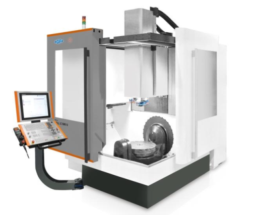
many CAD/CAM software packages offer automatic programming capabilities. These software packages typically provide prompts regarding process planning within the programming interface, such as tool selection, machining path planning, and cutting parameters. Once the programmer sets the relevant parameters, the software can automatically generate NC programs and transmit them to CNC machines for processing. Therefore, tool selection and determination of cutting parameters in CNC machining are completed in an interactive environment, which is in stark contrast to conventional machining. This also requires programmers to understand the basic principles of tool selection and cutting parameter determination. Programmers must consider the characteristics of CNC machining to correctly select tools and cutting parameters during programming. ### Common Types and Characteristics of Tools in CNC Machining CNC machining tools must be suited to the high speed and high automation characteristics of CNC machines. Generally, they include universal tools, standard tool holders, and a small number of specialized tool holders. The tool holders connect the tools to the machine's spindle, and as such, have gradually become standardized and serialized. There are various ways to classify CNC tools: - **By tool structure:**   1. Integral type  2. Inserted type, connected by welding or mechanical clamping (mechanical clamping can be non-indexable or indexable)  3. Special types, such as composite tools and damped tools - **By material:**   1. High-speed steel tools  2. Carbide tools  3. Diamond tools  4. Tools made from other materials, such as cubic boron nitride or ceramics - **By cutting process:**  1. Turning tools (external, internal, threading, grooving, etc.)  2. Drilling tools (drills, reamers, taps, etc.)  3. Boring tools  4. Milling tools To meet CNC machine requirements for durability, stability, ease of adjustment, and interchangeability, indexable insert tools have been widely adopted in recent years. These tools now constitute 30%–40% of all CNC tools, accounting for 80%–90% of the total metal removal volume. ### Requirements and Characteristics of CNC Tools Compared to tools used on conventional machines, CNC tools have specific requirements and characteristics:1. Good rigidity (especially for roughing tools), high precision, resistance to vibration, and minimal thermal deformation2. Good interchangeability to facilitate quick tool changes3. High durability and reliable cutting performance4. Adjustable dimensions to reduce tool change adjustment time5. Reliable chip breaking or curling for efficient chip removal6. Standardization and serialization to facilitate programming and tool management ### Tool Selection in CNC Machining Tool selection in CNC programming is conducted interactively. The correct selection of tools and tool holders depends on the machine’s capabilities, the material of the workpiece, the machining process, cutting parameters, and other relevant factors. The general principles for tool selection are ease of installation and adjustment, good rigidity, durability, and high precision. To enhance tool rigidity, shorter tool holders should be selected whenever possible, provided they meet the machining requirements. When selecting tools, their size should be appropriate for the surface dimensions of the workpiece. For example, flat end mills are commonly used for machining the contours of flat parts; carbide insert milling cutters are preferred for milling flat surfaces; high-speed steel end mills are used for machining bosses and grooves; corn milling cutters with carbide inserts are suitable for machining rough surfaces or pre-machined holes; ball nose end mills, ring mills, taper mills, and disc mills are typically used for machining complex surfaces and varying angle contours. In free-form surface (mold) machining, the cutting speed at the end of a ball-end tool is zero. Therefore, to ensure machining accuracy, the cutting path spacing is usually set closer at the top end, making ball-end tools suitable for finish machining of surfaces. Flat-end tools, however, are superior in surface machining quality and cutting efficiency. Hence, flat-end tools should be preferred for both roughing and finishing of surfaces, as long as overcutting can be avoided. The durability and precision of tools are significantly related to their cost. Notably, while high-quality tools increase tool costs, they also significantly enhance machining quality and efficiency, thereby reducing overall machining costs. In machining centers, various tools are mounted in the tool magazine and selected and changed as per the program's instructions. Therefore, standard tool holders must be used to ensure that standard tools for drilling, boring, reaming, and milling can be quickly and accurately mounted onto the machine spindle or tool magazine. Programmers need to understand the structural dimensions, adjustment methods, and adjustment ranges of the tool holders used on the machine to determine the radial and axial dimensions of the tools during programming. Currently, China's machining centers use the TSG tool system, which includes straight shank (three specifications) and tapered shank (four specifications) holders, covering a total of 16 types of tool holders for different applications. In the processing of economical CNC machines, where tool sharpening, measurement, and replacement are mostly done manually, the auxiliary time is relatively long. Therefore, the arrangement of tool sequences must be reasonable. The general principles to follow include:1. Minimize the number of tools.2. Each tool should complete all possible machining steps after being clamped once.3. Separate rough and finish machining tools, even if they have the same specifications.4. Mill first, then drill.5. Perform contour finishing after 3D surface finishing.6. Utilize the automatic tool change function of the CNC machine as much as possible to improve production efficiency. ### Determining Cutting Parameters in CNC Machining The principles for selecting cutting parameters reasonably are: prioritizing productivity during rough machining while considering economy and machining costs; balancing machining quality, cutting efficiency, and cost during semi-finishing and finishing. Specific values should be determined based on the machine's manual, cutting parameter manuals, and experience. Several factors need to be considered: 1. **Cutting depth (t):** When the machine, workpiece, and tool rigidity permit, t should equal the machining allowance, which is an effective measure to improve productivity. To ensure part precision and surface roughness, a certain amount of allowance should be left for finishing. The finishing allowance for CNC machines can be slightly less than that for conventional machines.2. **Cutting width (L):** Generally, L is proportional to the tool diameter (d) and inversely proportional to the cutting depth. For economical CNC machines, L typically ranges between 0.6d and 0.9d.3. **Cutting speed (v):** Increasing v is another measure to improve productivity. However, v closely relates to tool durability; as v increases, tool durability decreases sharply. Therefore, v is primarily determined by tool durability. Cutting speed also varies significantly with the material being machined. For instance, when milling alloy steel 30CrNi2MoVA with an end mill, v can be about 8 m/min, whereas for milling aluminum alloy with the same tool, v can exceed 200 m/min.4. **Spindle speed (n):** Spindle speed is usually determined by cutting speed (v) using the formula v = πnd/1000. CNC machines typically have a spindle speed override switch on the control panel to adjust spindle speed by multiples during machining.5. **Feed rate (vF):** vF should be chosen based on the required machining precision and surface roughness, as well as the tool and workpiece materials. Increasing vF can also improve productivity. When low surface roughness is required, a higher vF can be selected. During machining, vF can be manually adjusted using the override switch on the machine control panel, but the maximum feed rate is limited by the machine's rigidity and feed system performance. With the widespread application of CNC machines in production and the formation of quantitative production lines, CNC programming has become a key issue in CNC machining. During the preparation of CNC programs, tool selection and cutting parameter determination must be done interactively. Therefore, programmers must be familiar with tool selection methods and principles for determining cutting parameters to ensure part quality and machining efficiency, fully leverage the advantages of CNC machines, and improve the economic efficiency and production level of enterprises.
Service About us
Contact Us
Address: 18 Yingbin Road, Shanghai, China

  A specialized vertical platform for exporting Chinese machine tools, including both new and used machines. Since 2015, we have sold 20,356 machines and served over 120+ countries worldwide.

E-mail :Dy@2wedm.com
Contact Number: +86 13912795586